TOPIC 3: ELECTROMAGNET
3.1 MAGNETIC EFFECT OF A CURRENT-CARRYING CONDUCTOR
ELECTROMAGNET
- An electromagnet is a type of magnet in which the magnetic field is produced ba a flow of electric current. the magnetic field dissappears when the current ceases.

- An electromagnet can be made by sending an electric current through a coil of wire wound around an iron core.
- When a current flows through the coil, it produces a magnetic field.
- The soft iron core becomes temporarily magnetized when the current is switched on and attract the paper clips.
- When the current is switched off, it loses its magnetism (demagnetizes).
magnetic field pattern
- A magnetic field pattern can be represented by field lines that show the shape of the field.
- Magnetic field lines which are close together represent a strong field.
- The field direction is defined as the direction indicated by a compass needle placed in the magnetic field.

- The field direction can also be determined using The Right-Hand Grip Rule.
The Right-Hand Grip Rule.

- Grip the wire using the right hand, with your thumb pointing in the direction of the current.
- Your other fingers now point round the wire in the direction of the magnetic field.
- When the direction of the current is reversed, the magnetic field direction also is reversed.
- Top view


The direction of the
magnetic field around a coil

- The plotting compasses show the magnetic field pattern due to current in a circular coil.
- Top view

The direction of the magnetic field around a
solenoid

- Magnetic field pattern similar to a magnetic bar
- Field lines in the centre are close – strong field
- One end acts as north pole, whereas the other end acts as a south pole
- To determine the pole of magnetic field, use:

- Field lines move out from North pole and re-enter the South pole
Solenoid
Rule
- Look at the direction of current flow at the end of the solenoid.

FACTORS
THAT AFFECT THE STRENGTH OF ELECTROMAGNETIC FIELD
- Strength of the electromagnetic field increases with the number of turns of the coil.
Current:
- Strength of the electromagnetic field increases with current
application of Electromagnet
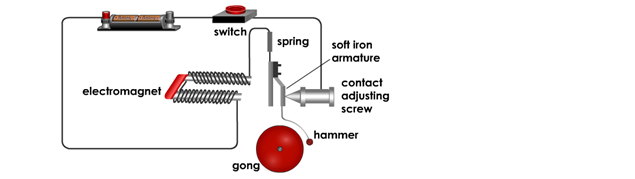
1. When the switch is pressed,
- a current flows in
the coils of the electromagnet
- causing it to be
magnetized.
2. The magnetized electromagnet
- attracts the
soft-iron armature,
- causing the hammer to
strike the gong.
3. The movement of the armature
- breaks the contact
- and causes the
electromagnet to lose it magnetism
4. The spring pulls the armature back,
- remaking the contact
- and completing the
circuit again.
Magnetic Relay

1. Circuit 1 requires only a small current.
2. When the switch is closed,
- small
current flows in the coil,
- causing
the soft-iron core to be magnetized and
attracts the armature
3. The movement of the iron armature
- closes
the contacts in the second circuit.
- Circuit
2 is now switched on.
4. Circuit 2 may have a
large current flowing through it to operate powerful motors or
very bright lights.
very bright lights.
5. The advantage of using a relay:
- a small
current (Circuit 1) can be used to switch on and off a circuit with a large
current (Circuit 2).
current (Circuit 2).
6. This is useful for two reasons:
- Circuit
1 may contain a component such as a light detecting resistor (LDR)
which uses small currents.
which uses small currents.
- Only
the circuit with a large current needs to be connected with thick wire.
Telephone Ear-piece

1.
The varying current from the microphone flows through the coils of an
electromagnet in the earpiece.
electromagnet in the earpiece.
2.
This pulls the diaphragm towards the electromagnet by a distance which depends
on the current.
on the current.
3.
As a result, the diaphragm moves in and out and produces sound waves that
are replicas of those that entered the microphone.
are replicas of those that entered the microphone.
Circuit Breaker
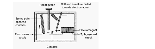
1.
Acts as an automatic switch that breaks open a circuit when the current
becomes too large.
becomes too large.
2.
In a household circuit, the current may become excessive when there is a short
circuit or an overload.
circuit or an overload.
3. The strength of the
magnetic field of the electromagnet increases suddenly.
4. The soft iron
armature is pulled towards the electromagnet.
5.
This results in the spring pulling apart the contacts. The circuit is broken
and
the current flow stops immediately.
the current flow stops immediately.
6.
After repairs have been made, the reset button is pushed to switch on the supply
again.
again.
3.2 FORCE ON A
CURRENT-CARRYING CONDUCTOR IN A MAGNETIC FIELD

- As the conductor is placed into the magnetic field of the permanent magnet, this
- results in the combination of two magnetic fields


- Resultant magnetic field at the left is
stronger than the on the right.
- Magnetic force is exerted on the conductor to
the right, thus the conductor is
pushed to the right.
pushed to the right.
- The force is called catapult force.
FLEMING’S LEFT- HAND RULE

- The force is caused by the combination of the
magnetic fields due to the current
carrying conductor ant the permanent
magnets.
FLEMING’S LEFT- HAND RULE
- Forefinger, second finger and the thumb of
the left hand are extended at right angles
to each other,
- Forefinger in the direction of the magnetic
field, the second finger in the direction of
the current, then the thumb will
point the direction of the force, F or motion
Exercise

Determine the direction of magnetic force act on
current carrying conductor PQ,using
Fleming’s Left - Hand Rule
DC MOTOR


Commutator
:
reverse
the direction of current in the coil every half rotation so that the coil
continues
to turn in same direction
to turn in same direction
Carbon
Brush:
to
contact with the commutator so the current from the battery enters the coil.

permanent magnet
a) Catapult field formed
b) PQ experience downward force
c) RS experience upward force
Force on PQ and RS are
a) equal in magnitude
b) opposite direction


The coil rotate in
anticlockwise direction.
Factors which affect the speed of rotation of the motor
Factors which affect the speed of rotation of the motor

Application of the Force on Current carrying conductor in a Magnetic field
a)
Moving
coil loudspeaker
b)
Moving coil
meter

3.3 ELECTROMAGNETIC
INDUCTION
Electromagnetic
Induction in a straight wire

1.
Current is induced in a straight conductor when it moves and
cuts the
magnetic field lines.
magnetic field lines.
2.
The motion of the copper rod must be perpendicular to the
direction of
the magnetic field lines so that an induced current will be produced.
the magnetic field lines so that an induced current will be produced.
Electromagnetic Induction in a solenoid
Current
is induced in a solenoid when there is relative motion between
the solenoid and a magnet.
the solenoid and a magnet.


Indicate the direction of the induced current in a straight wire
Fleming’s right-hand rule:

The
thumb and the first two fingers on the right hand are held at right angles
to each other
to each other
a)
the first finger pointing in the direction of the
magnetic field and
b)
the thumb in the direction of the motion,
c)
then the second finger points in the direction of the induced
current.

Wire
PQ is moved vertically downwards in a magnetic field. Applying Fleming’s
right-hand rule, the induced current will flow from P to Q.
Indicate
the direction of the induced current in a solenoid.
Lenz’s Law:
The direction
of the induced current in a solenoid is such that its magnetic
effect always oppose the change producing it.
effect always oppose the change producing it.
Magnet
is moved towards the solenoid

Magnet
is moved away from the solenoid

Factors
that affect the magnitude of the induced current
Faraday’s Law:
The size
of the induced e.m.f is directly proportional to the rate at which the
conductor cuts through the magnetic field lines.
conductor cuts through the magnetic field lines.
The
size of the induced current increased by:
1. increasing
the speed of moving magnet or solenoid
2. increasing
the number of turns on the solenoid
3. increasing
the strength of the magnetic field through the use of a
stronger magnet.
applications of electromagnetic induction
Current
Generator
• Current generator
functions by converting mechanical energy to electrical energy.
• Current generator
works based on electromagnetic induction and uses the
Fleming’s Right hand rule.
• Current generator is
divided into: direct current generator and alternate
current generator.
Direct
Current Generator

Commutator: reverses
the connections of the coil with the external circuit
after every half cycle,
so that the current in the outside circuit always flows
in the same direction


Peak current and peak voltage


Alternating
Current Generator
The two
ends of the coil are connected to two slip rings which rotate with the coil.
• Each slip ring is
always in contact with the same carbon brush.
The
output current generated is an alternating current because the current
changes
direction in the external circuit each time the coil passes the
vertical
position.
• Assume the current
flows from P to Q is positive and the current flows from
Q to P is negative.
• The current changes
magnitude and direction after every half rotation.
Compare direct current and alternating current
Direct current (d.c)
|
Alternating current (a.c)
|
Flows in one direction only in a circuit
|
Flows to and fro in two opposite directions in a circuit.
Changes its direction periodically
|
 |
 |

Can flow through a resistor but cannot flow through a capacitor.
|

can flow through both a resistor and a capacitor.
|
Both
the direct current and alternating current have a heating effect on the
filament of a bulb and can light up the bulb.
|
|
Peak current and peak voltage
The
current increases from zero to a maximum value of +I0 (at A), and back
to zero at B. It
then reverses direction and increases to -I0 (at C) and back
to zero again.
I0 = peak
current,
V0 = peak
voltage
• The time taken for a
complete cycle from O to D is called one period, T.
• Frequency of the current is f where f = 1
T
• In Malaysia, the
frequency of the a.c supply is 50 Hz. Hence, the period
of the a.c is
: T = 1/50 = 0.02 seconds
exercise

Figure
shows an alternating current with a magnitude that changes with time.
(a) What
is the peak current?
(b) What
is the period of the a.c. current?
(c) What
is the frequency of the a.c current?


3.4 TRANSFORMER
A transformer is an electrical device which
increases or decreases an
alternating voltage based on the principle of
electromagnetic induction.
Structure of a simple transformer.
- A transformer consists of two coils of wire
wound round separately on a
laminated soft-iron core.


- The coil connected to the input voltage is
called the primary coil. The coil
connected to the output voltage is called the
secondary coil.
- The purpose of the common iron core is to
provide a magnetic field linkage
in the secondary coil.
Symbol of a simple transformer
Operating principle of a simple transformer
The changing magnetic field produced by
primary coil induces an alternating
current in the secondary coil.
- A transformer works on the principle of
electromagnetic induction.
- When a.c voltage, Vp, is applied to the
primary coil of transformer, an
alternating current flows through the coil. The
soft-iron core is magnetized
in one way and then the other.
- e.m.f is induced across it to produce an a.c
voltage, Vs in the secondary
coil and a.c current flows through the second
coil.
- The frequency of the secondary voltage Vs is
the same as that of the
primary voltage, Vp.
- The magnitude of the secondary voltage, Vs,
depends on the ratio of the
number of turns of the primary and secondary coils.
Relationship between number of turns in coils
with voltage in a transformer,
(Vp, Np, Vs and Ns)
According to
Faraday’s law:
No comments:
Post a Comment